So you have lost your MikroTik radio's adapter and you really need connection right now! It is easy. Well, as long as you have the MikroTik Router with the yellow port.
Connect the cable from the radio to the yellow port (5) and login into the router and do the following;
1. Go to Interfaces, then select ether5-slave-local.
Change on Master Port to be none.
Change the name to something else like ether5. Make sure the word slave is not there because the NAT rule won't accept a slave port.
Apply then Ok and that is done
2. Go to IP>Firewall and choose NAT.
Choose the Out. Interface to be ether5
And you are done. Enjoy the connection.
Showing posts with label New Learned. Show all posts
Monday, April 25, 2016
Monday, July 20, 2015
Port Forwarding - ZyXEL - NBG419N (ZyXEL Firmware)
Step 1.
Some routers & modems work best with port forwarding if you have a static local IP.
Manually set your network interface card (NIC) to use a static ip address.
Step 2.
Open your favorite web browser and input your routers ip address in the address bar.
Please note that you must have the http:// in order to connect to your router/modem properly.
Step 3.
Enter the routers password and click the Login button.
Step 2.
Open your favorite web browser and input your routers ip address in the address bar.
Please note that you must have the http:// in order to connect to your router/modem properly.
Step 3.
Enter the routers password and click the Login button.
If you have changed it and don't remember it you may have to reset your device to factory default using the reset button on most routers.
Step 4.
At the Welcome page click the "Go" button.
Once the page loads click the "Expert Mode" button at the top of the page.
Step 5
Once the page loads click the "Configuration" tab at the left of the screen.
Step 6
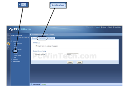
Once the page loads click the "NAT" link listed under "Network".
Now click the "Application" tab at the top of the page.

Step 7
Once the page loads listed under "Add Application Rule" check the "Active" box.
Once the page loads click the "NAT" link listed under "Network".
Now click the "Application" tab at the top of the page.
Step 7
Once the page loads listed under "Add Application Rule" check the "Active" box.
Now for "Service Name" give your rule a name, and select "User Defined" from the list.
For "Port" enter the port you want to forward.
For "Server IP Address" enter the IP of the computer you want to forward to.
Now Click the "Apply" button.
Monday, February 9, 2015
Install, Reinstall or Reset MikroTiK RouterOS: NetInstall
Sometimes the radio/ router becomes half past dead due to some causes. It receives power and that's all. It won't bring data. You have done the hard reset but nothing. Instead of throwing it away and declare it dead, you can revive it.
There is this program that is called NetInstall that runs on Windows computer that allows you to install, reinstall or reset MikroTiK RouterOS onto a PC or onto a RouterBOARD via an Ethernet cable.
What is required is;
You must have the program on your pc.
Your device must support booting from ethernet, and there must be a direct ethernet link from the Netinstall computer to the target device. All RouterBOARDs support network booting from Ether1 port.
Netinstall can also directly install RouterOS on a disk (USB/CF/IDE/SATA) that is connected to the Netinstall Windows machine. After installation just move the disk to the Router machine and boot from it.
Here are the steps;
1. Connect the MikroTik device to your pc using Ethernet cable
2. Run NetInstall
3. Now go to your network card and add ip
4. Go to NetInstall and click on Net Booting tab. On the window that has appeared, put an ip address on the same range as the ip you have put on your network card. Note: Not the same IP but the same range.
5. Then click Browse to select on your PC the OS to be installed on device (you must have downloaded it).
6. Now the hard reset part.
If the device is not displayed on Routers/Drives, it should after the successful hard reset.
7. Now select the device and the OS to be installed and click install tab
ANd the NetInstall part is done
Your device is revived now but it comes with 0.0.0.0 as IP address and other things like wireless interface are disabled.
You should reset it normally (not the hard reset)
and you are done.
There is this program that is called NetInstall that runs on Windows computer that allows you to install, reinstall or reset MikroTiK RouterOS onto a PC or onto a RouterBOARD via an Ethernet cable.
What is required is;
You must have the program on your pc.
Your device must support booting from ethernet, and there must be a direct ethernet link from the Netinstall computer to the target device. All RouterBOARDs support network booting from Ether1 port.
Netinstall can also directly install RouterOS on a disk (USB/CF/IDE/SATA) that is connected to the Netinstall Windows machine. After installation just move the disk to the Router machine and boot from it.
Here are the steps;
1. Connect the MikroTik device to your pc using Ethernet cable
2. Run NetInstall
3. Now go to your network card and add ip
4. Go to NetInstall and click on Net Booting tab. On the window that has appeared, put an ip address on the same range as the ip you have put on your network card. Note: Not the same IP but the same range.
5. Then click Browse to select on your PC the OS to be installed on device (you must have downloaded it).
6. Now the hard reset part.
If the device is not displayed on Routers/Drives, it should after the successful hard reset.
7. Now select the device and the OS to be installed and click install tab
ANd the NetInstall part is done
Your device is revived now but it comes with 0.0.0.0 as IP address and other things like wireless interface are disabled.
You should reset it normally (not the hard reset)
and you are done.
Monday, February 2, 2015
Chatting in MikroTik
You are at your client troubleshooting their connection and there are some things that give you a hard time.
You want to make a call for assistant from your colleagues but you think that is so unprofessional in front of your client.
MikroTik can help you communicate with others!
Two or more admin can chat with each other through mikroTik's terminal
The only thing you need to do is to write your message after # sign and that's it,
other terminal user see your message
Example : #Ahmaizing!
Have fun
You want to make a call for assistant from your colleagues but you think that is so unprofessional in front of your client.
MikroTik can help you communicate with others!
Two or more admin can chat with each other through mikroTik's terminal
The only thing you need to do is to write your message after # sign and that's it,
other terminal user see your message
Example : #Ahmaizing!
Have fun
Thursday, July 24, 2014
MikroTik: Wireless Repeater
A wireless repeater (also called wireless range extender) takes an existing signal from a wireless router or access point and rebroadcasts it to create a second network.
After you have configured your MikroTik router and you want to extend the wireless accessibility, here are few simple steps you need to follow to configure the other router as a repeater;
1.a) Let us say your wireless SSID of the first router is MainRouter.
On the Repeater go to wireless interface and scan to connect to the first router. If this is successful then on SSID you will see the name of the first router "MainRouter".
b) Configure the Wireless Distribution System.
While still in the Wireless Interface, Click on WDS and select Dynamic on WDS Mode. And WDS Default Bridge should be Bridge-Local, if you have configured your local IP Address on it.
2. a) Now add the Virtual Interface by clicking on the + sign and selecting VirtualAP. It should appear as Wlan2. Click the Interface to configure Wireless SSID. Let us call the SSID: To_Clients. Master interface should be wlan1.
b)Then, Configure the WDS of Wlan2 as you have configured the previous one.
3. Go to Bridge and add ports ; wlan2 and wds2 if they did not appear by default.
4. If the main router had 192.168.88.1, then give the repeater another IP, say 192.168.88.2 it should work fine without IP but put it anyway to avoid confusions.
5. Go to wireless Security Profile and make sure that it has the same keys as the main router.
And there you go! Enjoy the Looong range of your wireless network.
After you have configured your MikroTik router and you want to extend the wireless accessibility, here are few simple steps you need to follow to configure the other router as a repeater;
1.a) Let us say your wireless SSID of the first router is MainRouter.
On the Repeater go to wireless interface and scan to connect to the first router. If this is successful then on SSID you will see the name of the first router "MainRouter".
b) Configure the Wireless Distribution System.
While still in the Wireless Interface, Click on WDS and select Dynamic on WDS Mode. And WDS Default Bridge should be Bridge-Local, if you have configured your local IP Address on it.
2. a) Now add the Virtual Interface by clicking on the + sign and selecting VirtualAP. It should appear as Wlan2. Click the Interface to configure Wireless SSID. Let us call the SSID: To_Clients. Master interface should be wlan1.
b)Then, Configure the WDS of Wlan2 as you have configured the previous one.
3. Go to Bridge and add ports ; wlan2 and wds2 if they did not appear by default.
4. If the main router had 192.168.88.1, then give the repeater another IP, say 192.168.88.2 it should work fine without IP but put it anyway to avoid confusions.
5. Go to wireless Security Profile and make sure that it has the same keys as the main router.
And there you go! Enjoy the Looong range of your wireless network.
Friday, May 2, 2014
How to setup Website Filter on D-Link DIR series router DIR-655
To setup Website Filter on D-Link DIR-655 Router.
Step 1: Open your web browser and type in the IP address of the router (192.168.0.1 by default).
Step 2: Enter the username (admin) and password (blank by default), and then click Ok or Log In .
Step 3: Click the Advance Tab and Website Filter on the left hand side of the screen. Select the option “Deny computers access to ONLY these sites” under Configure Website Filter below. You will be indicating what websites should be blocked or restricted on this router. Once your done click Save Settings.
Step 4: Next go-to the Access Control Tab and check the box to Enable Access Control. On Access Control you will need to setup a policy on the router for the Website Filter. Click Add Policy and follow the wizard.
Step 5: Click Next.
Step 6: Name the policy and click Next.
Step 7: Select a schedule and click Next.
Step 8: Select the machine(s) to which this policy applies by IP or MAC address and click Next.
Step 9: Select Filtering Method and click Next.
Step 10: Enable or Disable Web Access Logging and click Next.
Step 11: You should now see the policy listed at the bottom under Policy Table. Click Save Settings.
Step 1: Open your web browser and type in the IP address of the router (192.168.0.1 by default).
Step 2: Enter the username (admin) and password (blank by default), and then click Ok or Log In .
Step 3: Click the Advance Tab and Website Filter on the left hand side of the screen. Select the option “Deny computers access to ONLY these sites” under Configure Website Filter below. You will be indicating what websites should be blocked or restricted on this router. Once your done click Save Settings.
Step 4: Next go-to the Access Control Tab and check the box to Enable Access Control. On Access Control you will need to setup a policy on the router for the Website Filter. Click Add Policy and follow the wizard.
Step 5: Click Next.
Step 6: Name the policy and click Next.
Step 7: Select a schedule and click Next.
Step 8: Select the machine(s) to which this policy applies by IP or MAC address and click Next.
Step 9: Select Filtering Method and click Next.
Step 10: Enable or Disable Web Access Logging and click Next.
Step 11: You should now see the policy listed at the bottom under Policy Table. Click Save Settings.
Tuesday, March 18, 2014
Configuring MikroTik Router
Winbox or browser can be used to do this.
The demonstration here below is by using Winbox.
1. Go to Wireless tab on the left hand-side. on the screen that appears, choose the interface that is there and go to WIRELESS on the screen that has appeared.
The Mode by default is AP-bridge, and that is what it should be.
On SSID is where you put the name of the wireless you prefer
Next go to WDS Tab
configure as the image below demonstrates
2. While you are still on Wireless
Go to SECURITY PROFILE and click on the default interface that is there
WPA and WPA2 Pre-shared key is where you put your wireless security key/password
3. To configure IP Addresses, go to IP on the left handside of the screen and then choose ADDRESSES
Configure the public IP on ether1-gateway interface and private IP on the bridge-local interface
4. To configure the GATEWAY, Go to IP then ROUTES
Click the + sign to add the gateway interface. on the screen appeared, type the gateway on the gateway space
5. To configure DNS, go to IP then DNS.
On the screen that appears, type the DNS on the Servers space.
6. To configure the DHCP, go to IP then DHCP Server.
On the screen that appears, choose DHCP Setup and click next, next,.... if you have no changes to make. make sure the DHCP interface is the one you configured the private IP address.
And you are done.
ENJOY THE INTERNET :-)
1. Go to Wireless tab on the left hand-side. on the screen that appears, choose the interface that is there and go to WIRELESS on the screen that has appeared.
The Mode by default is AP-bridge, and that is what it should be.
On SSID is where you put the name of the wireless you prefer
Next go to WDS Tab
configure as the image below demonstrates
2. While you are still on Wireless
Go to SECURITY PROFILE and click on the default interface that is there
WPA and WPA2 Pre-shared key is where you put your wireless security key/password
3. To configure IP Addresses, go to IP on the left handside of the screen and then choose ADDRESSES
Configure the public IP on ether1-gateway interface and private IP on the bridge-local interface
4. To configure the GATEWAY, Go to IP then ROUTES
Click the + sign to add the gateway interface. on the screen appeared, type the gateway on the gateway space
5. To configure DNS, go to IP then DNS.
On the screen that appears, type the DNS on the Servers space.
6. To configure the DHCP, go to IP then DHCP Server.
On the screen that appears, choose DHCP Setup and click next, next,.... if you have no changes to make. make sure the DHCP interface is the one you configured the private IP address.
And you are done.
ENJOY THE INTERNET :-)
Thursday, September 5, 2013
Factors Affecting Wireless Networking Performance
There are many factors that affect your Wireless Networking Performance that are dependent on various areas within the network itself from the technology of the devices used, the local environment the signals will travel through, the fundamental physics behind wireless transmission and more. Some of these cannot be avoided and measures must be taken to try to minimise the negative affect that these factors will have on the network performance but others can be resolved completely either though equipment upgrading or good network planning.
There are some well known factors that affect Wireless Networking performance that most people will identify easily but that does not lessen their importance when considering network planning, these are:
Obvious Factors Affecting Wireless Networking Performance
Physical Obstructions
Network Range & Distance between Devices
Wireless Network Interference
Signal Sharing
Quite Well Known Factors Affecting Wireless Networking Performance
Network Usage & Load
Poorly Deployed Antennas
Local Environment Characteristics
Spectrum Channel Limitations
Signal Reflection
Wireless Signal Restriction
Lesser Known Factors Affecting Wireless Networking Performance
Transmitter Power Limitations
Backwards Compatibility with Older Standards
Polarisation of Signal
Speed Loss Due to Wireless Overheads
Lowering Performance to Stay Connected
The Obvious Factors Affecting Wireless Networking Performance
Physical Obstructions
Wireless signals can have trouble penetrating solid objects which can be any numbers of things such as hills, buildings, single walls or even people. The more obstructions you have between the transmitter and receiver, the more chance there is that the signal strength will be affected so you should try and maintain as clearer line of site as possible. This is obviously not practical in the real world as there is nearly always something in the way but you can minimise the effect it will have by using specific frequencies available to you. As a rule, the lower the frequency, the better penetration characteristics the waves have. However, it also runs that the higher the frequency, the better the reflective capabilities of the wave, so in some cases reflecting a signal to the receiver may work better than trying to send it through objects i.e. walls.
Network Range & Distance Between Devices
The further apart the networked devices that are trying to communicate with each other are, the more the signal strength drops. This is due to way that wireless signals propagate covering a wider area as they travel further and because of this, as the signal spreads more, the weaker it becomes. The signal strength decreases, roughly, in an inverse cubic relation with respect to the distance between the two devices.
Strength = 1/Distance^3
i.e if Distance=1m then Strength=1/1^3 = 1/1 = 1
i.e if Distance=2m then Strength=1/2^3 = 1/8 = 0.125
Therefore as the distance has doubled; the signal becomes 8 times weaker.
Wireless Network Interference
Wireless Networking is becoming more and more common and therefore more wireless transmissions are being sent through the air. Signals operating at similar frequencies can cause interference with each other and have a significantly negative effect on the performance of the network. This means that more popularly used frequency bands such as the 2.4GHz unlicensed band can get severely affected by the overcrowding of wireless signals to a point where a device will not operate at an acceptable level. Other wireless technologies can cause identical interference such as mobile phones and microwave ovens that operate within the same ranges. More frequency bands are becoming available to operate in to avoid this issue such as the unlicensed 5GHz frequency band that is becoming popular. When operating in areas of high wireless network densities, it is advised that you work with businesses, operators etc. around you to avoid future interference problems.
Signal Sharing
Wireless Networks allow more than 1 person to communicate with another network source at any one time. This sharing of connection means that the more subscribers utilising the network, the more devices the access point has to try and communicate with instantaneously. The point of access has to delegate its resources to each subscriber individually per the amount of transmitting radios it operates on. Full-Duplex capable equipment can transmit and receive data simultaneously whereas Half-Duplex equipment can only send or receive at any one time.
The Quite Well Known Factors Affecting Wireless Networking Performance
Network Usage & Load
You will find that the more clients that are utilising the network bandwidth, the less that there is to share between them. As bandwidth requirements increase on your network (video streaming is one bandwidth intensive application), you may want to invest in equipment that can cater for high throughput speeds to keep the performance and network reliability at a high level.
Poorly Deployed Antennas
As antennas work by limiting the spread of transmitted signals to a specific direction or orientation, they must be installed and mounted correctly to improve network performance. The most obvious is the highly directional antenna type that must be pointed directly at the receiver in order for the signal to be picked up but other types of antenna must be orientated correctly to ensure that they are transmitting signal on the correct plane. Sector antennas usually have a vertical or horizontal plane that they operate on and Omni-Directional antennas will only transmit signal well on one plane but in all directions.
Local Environment Characteristics
Most prominently affecting indoor networks, wall construction properties can be one of the biggest inhibiters of wireless signals. Wire meshing within the walls can cripple signal transmissions and the materials used have different levels of effect; concrete is a usual suspect in badly performing indoor networks. It almost goes without saying that the thicker the walls, the less success the signal will have penetrating through it whilst maintaining a high strength.
Spectrum Channel Limitations
This typically only affects Wireless Networks that operate at only popular frequency bands such as 2.4GHz but may start to affect the 5GHz band in the future if people migrate en masse. Wireless Networks operate on frequency sub-bands know as channels that are of smaller bandwidths within their overall possible operating frequencies. The 2.4GHz band is split up into 11 channels operating on bandwidths of 25MHz each spaced 5MHz apart, within an overall range of 2412MHz to 2462MHz. It doesn't take much maths to work out that the channels have to overlap each other to be able to fit within the overall operating range. This overlapping causes interference if wireless devices are using neighbouring channels and so the only channels recommended for use are 1, 6 and 11 as these do not overlap. However, this means that only 3 wireless devices can used within the same area unless overlapping channels are to be used.
Signal Reflection
Signal reflection, known technically as Multi-Path Fade, occurs typically in buildings that have complex and intricate structural layouts. The different paths the signals take when being transmitted can be reflected off of surroundings causing differences in overall path distance lengths on their way to the receiver. When these varying signals reach the receiver they can be out of phase with each other and this can cause the overlapping waves in question to either enlarge the signal amplification or can completely cancel out each other. Also the times at which the reflected signals reach the receiver are different due to the varying distances in the RF Paths they have travelled to get there. The spread in the delay between the signals creates ISI (Intersymbol Interference) which is a situation in which the delayed signals begin to corrupt the symbols travelling on a shorter RF Path. These problems can be overcome by using diversity antennas (installing more than 1 antenna on the transmitter at specific distances apart) which ensures that if one antenna is performing poorly, the other will most likely be okay or by using technology such as OFDM which can cure this by introducing subcarrier channels within each main channel. These sub-carrier channels send and receive date simultaneously in parallel with each other and the many, smaller channels ensure that more data can be transferred with lower levels of loss due to signal interference.
Wireless Signal Restriction
For security reasons you may want to restrict the transmission of your wireless signal to only the areas that you want to provide network access for. This can be troublesome as controlling signal propagation is not easy as it can travel through walls into other buildings or outside areas where someone could try to connect without authorisation. Limiting transmitter power levels to only cover the required area is one method of solving this issue but it has the knock on effect that signal strengths will be weaker to all receiving devices. Using directional antennas to limit the signal spread can also be effective in limiting the area in which the signal covers.
Lesser Known Factors Affecting Wireless Networking Performance
Transmitter Power Limitations
Regulations set by OFCOM dictate that the devices operating on certain frequency ranges must adhere to maximum transmitter output power levels. These values change depending on what frequency your devices are operating on with, for example, 2.4GHz being 100mW E.I.R.P and 5GHz being between 200mW - 4W E.I.R.P; so you can see that for different bands, you can operate on different power levels. This has a large effect on signal strength and in most cases, networks benefit from having the devices operating on as higher power levels as regulations allow, increasing signal strength over longer distances. If directional, gain antennas are used the operating power levels may have to be turned down because OFCOM declares maximum limits to the relative signal strength produced by the radio and antenna combination. If using a highly directional, pencil beam type antenna, the radio's power levels may have to be reduced significantly to keep the wireless transmission within the maximum signal strength regulations.
Backwards Compatibility with Older Standards
Currently this is only having a major effect on networks operating on 802.11 standards. If you have a mixture of devices that are 802.11n and some that are only 802.11b or g, the new technology has to limit itself to the maximum throughput speeds of the old b and g devices. It is advised that if you want to experience the full potential of new standards of technology, you replace all existing, old devices that could restrict your network performance.
i.e.
Max Speed on 2.4GHz Network with 802.11b device present: 11Mbps
Max Speed on 2.4GHz Network with 802.11g device present & no 802.11b devices: 54Mbps
Max Speed per Stream on 2.4GHz Network with only 802.11n devices: 150Mbps
Polarisation of Signal
Antennas polarise their transmitted signals and therefore receiving devices should be orientated to receive the signal on the same plane for the optimum performance. This is essential in the installation of high throughput, mission critical, Point-to-Point Ethernet Bridge Links.
Speed Loss Due to Wireless Overheads
Due to encryption, packet translation and partial utilisation of channel bandwidth for user data, advertised throughput speeds are not the actual, real world throughput speeds experienced by the end user. Wireless networking protocol overheads typically result in maximum throughputs of half the maximum theoretical speeds advertised and this can then be further reduced by other factors relating to the makeup of the data packets. Basically, the maximum advertised speeds are in general much higher than what you will probably experience but some manufactures are listing "real world" speeds on their products to give customers a better idea at what they can expect to achieve.
Lowering Performance to Stay Connected
Some Wireless Networking devices can reduce the operating throughput speeds to devices as to remain connected in areas of low signal due to increased distance between devices or interference etc. This affects the whole network and other users connected to it because of the increased time of data transmissions between the slower devices. Also the retransmission of data because of dropped packets limits the availability of the access point for communication with other clients.
There are some well known factors that affect Wireless Networking performance that most people will identify easily but that does not lessen their importance when considering network planning, these are:
Obvious Factors Affecting Wireless Networking Performance
Physical Obstructions
Network Range & Distance between Devices
Wireless Network Interference
Signal Sharing
Quite Well Known Factors Affecting Wireless Networking Performance
Network Usage & Load
Poorly Deployed Antennas
Local Environment Characteristics
Spectrum Channel Limitations
Signal Reflection
Wireless Signal Restriction
Lesser Known Factors Affecting Wireless Networking Performance
Transmitter Power Limitations
Backwards Compatibility with Older Standards
Polarisation of Signal
Speed Loss Due to Wireless Overheads
Lowering Performance to Stay Connected
The Obvious Factors Affecting Wireless Networking Performance
Physical Obstructions
Wireless signals can have trouble penetrating solid objects which can be any numbers of things such as hills, buildings, single walls or even people. The more obstructions you have between the transmitter and receiver, the more chance there is that the signal strength will be affected so you should try and maintain as clearer line of site as possible. This is obviously not practical in the real world as there is nearly always something in the way but you can minimise the effect it will have by using specific frequencies available to you. As a rule, the lower the frequency, the better penetration characteristics the waves have. However, it also runs that the higher the frequency, the better the reflective capabilities of the wave, so in some cases reflecting a signal to the receiver may work better than trying to send it through objects i.e. walls.
Network Range & Distance Between Devices
The further apart the networked devices that are trying to communicate with each other are, the more the signal strength drops. This is due to way that wireless signals propagate covering a wider area as they travel further and because of this, as the signal spreads more, the weaker it becomes. The signal strength decreases, roughly, in an inverse cubic relation with respect to the distance between the two devices.
Strength = 1/Distance^3
i.e if Distance=1m then Strength=1/1^3 = 1/1 = 1
i.e if Distance=2m then Strength=1/2^3 = 1/8 = 0.125
Therefore as the distance has doubled; the signal becomes 8 times weaker.
Wireless Network Interference
Wireless Networking is becoming more and more common and therefore more wireless transmissions are being sent through the air. Signals operating at similar frequencies can cause interference with each other and have a significantly negative effect on the performance of the network. This means that more popularly used frequency bands such as the 2.4GHz unlicensed band can get severely affected by the overcrowding of wireless signals to a point where a device will not operate at an acceptable level. Other wireless technologies can cause identical interference such as mobile phones and microwave ovens that operate within the same ranges. More frequency bands are becoming available to operate in to avoid this issue such as the unlicensed 5GHz frequency band that is becoming popular. When operating in areas of high wireless network densities, it is advised that you work with businesses, operators etc. around you to avoid future interference problems.
Signal Sharing
Wireless Networks allow more than 1 person to communicate with another network source at any one time. This sharing of connection means that the more subscribers utilising the network, the more devices the access point has to try and communicate with instantaneously. The point of access has to delegate its resources to each subscriber individually per the amount of transmitting radios it operates on. Full-Duplex capable equipment can transmit and receive data simultaneously whereas Half-Duplex equipment can only send or receive at any one time.
The Quite Well Known Factors Affecting Wireless Networking Performance
Network Usage & Load
You will find that the more clients that are utilising the network bandwidth, the less that there is to share between them. As bandwidth requirements increase on your network (video streaming is one bandwidth intensive application), you may want to invest in equipment that can cater for high throughput speeds to keep the performance and network reliability at a high level.
Poorly Deployed Antennas
As antennas work by limiting the spread of transmitted signals to a specific direction or orientation, they must be installed and mounted correctly to improve network performance. The most obvious is the highly directional antenna type that must be pointed directly at the receiver in order for the signal to be picked up but other types of antenna must be orientated correctly to ensure that they are transmitting signal on the correct plane. Sector antennas usually have a vertical or horizontal plane that they operate on and Omni-Directional antennas will only transmit signal well on one plane but in all directions.
Local Environment Characteristics
Most prominently affecting indoor networks, wall construction properties can be one of the biggest inhibiters of wireless signals. Wire meshing within the walls can cripple signal transmissions and the materials used have different levels of effect; concrete is a usual suspect in badly performing indoor networks. It almost goes without saying that the thicker the walls, the less success the signal will have penetrating through it whilst maintaining a high strength.
Spectrum Channel Limitations
This typically only affects Wireless Networks that operate at only popular frequency bands such as 2.4GHz but may start to affect the 5GHz band in the future if people migrate en masse. Wireless Networks operate on frequency sub-bands know as channels that are of smaller bandwidths within their overall possible operating frequencies. The 2.4GHz band is split up into 11 channels operating on bandwidths of 25MHz each spaced 5MHz apart, within an overall range of 2412MHz to 2462MHz. It doesn't take much maths to work out that the channels have to overlap each other to be able to fit within the overall operating range. This overlapping causes interference if wireless devices are using neighbouring channels and so the only channels recommended for use are 1, 6 and 11 as these do not overlap. However, this means that only 3 wireless devices can used within the same area unless overlapping channels are to be used.
Signal Reflection
Signal reflection, known technically as Multi-Path Fade, occurs typically in buildings that have complex and intricate structural layouts. The different paths the signals take when being transmitted can be reflected off of surroundings causing differences in overall path distance lengths on their way to the receiver. When these varying signals reach the receiver they can be out of phase with each other and this can cause the overlapping waves in question to either enlarge the signal amplification or can completely cancel out each other. Also the times at which the reflected signals reach the receiver are different due to the varying distances in the RF Paths they have travelled to get there. The spread in the delay between the signals creates ISI (Intersymbol Interference) which is a situation in which the delayed signals begin to corrupt the symbols travelling on a shorter RF Path. These problems can be overcome by using diversity antennas (installing more than 1 antenna on the transmitter at specific distances apart) which ensures that if one antenna is performing poorly, the other will most likely be okay or by using technology such as OFDM which can cure this by introducing subcarrier channels within each main channel. These sub-carrier channels send and receive date simultaneously in parallel with each other and the many, smaller channels ensure that more data can be transferred with lower levels of loss due to signal interference.
Wireless Signal Restriction
For security reasons you may want to restrict the transmission of your wireless signal to only the areas that you want to provide network access for. This can be troublesome as controlling signal propagation is not easy as it can travel through walls into other buildings or outside areas where someone could try to connect without authorisation. Limiting transmitter power levels to only cover the required area is one method of solving this issue but it has the knock on effect that signal strengths will be weaker to all receiving devices. Using directional antennas to limit the signal spread can also be effective in limiting the area in which the signal covers.
Lesser Known Factors Affecting Wireless Networking Performance
Transmitter Power Limitations
Regulations set by OFCOM dictate that the devices operating on certain frequency ranges must adhere to maximum transmitter output power levels. These values change depending on what frequency your devices are operating on with, for example, 2.4GHz being 100mW E.I.R.P and 5GHz being between 200mW - 4W E.I.R.P; so you can see that for different bands, you can operate on different power levels. This has a large effect on signal strength and in most cases, networks benefit from having the devices operating on as higher power levels as regulations allow, increasing signal strength over longer distances. If directional, gain antennas are used the operating power levels may have to be turned down because OFCOM declares maximum limits to the relative signal strength produced by the radio and antenna combination. If using a highly directional, pencil beam type antenna, the radio's power levels may have to be reduced significantly to keep the wireless transmission within the maximum signal strength regulations.
Backwards Compatibility with Older Standards
Currently this is only having a major effect on networks operating on 802.11 standards. If you have a mixture of devices that are 802.11n and some that are only 802.11b or g, the new technology has to limit itself to the maximum throughput speeds of the old b and g devices. It is advised that if you want to experience the full potential of new standards of technology, you replace all existing, old devices that could restrict your network performance.
i.e.
Max Speed on 2.4GHz Network with 802.11b device present: 11Mbps
Max Speed on 2.4GHz Network with 802.11g device present & no 802.11b devices: 54Mbps
Max Speed per Stream on 2.4GHz Network with only 802.11n devices: 150Mbps
Polarisation of Signal
Antennas polarise their transmitted signals and therefore receiving devices should be orientated to receive the signal on the same plane for the optimum performance. This is essential in the installation of high throughput, mission critical, Point-to-Point Ethernet Bridge Links.
Speed Loss Due to Wireless Overheads
Due to encryption, packet translation and partial utilisation of channel bandwidth for user data, advertised throughput speeds are not the actual, real world throughput speeds experienced by the end user. Wireless networking protocol overheads typically result in maximum throughputs of half the maximum theoretical speeds advertised and this can then be further reduced by other factors relating to the makeup of the data packets. Basically, the maximum advertised speeds are in general much higher than what you will probably experience but some manufactures are listing "real world" speeds on their products to give customers a better idea at what they can expect to achieve.
Lowering Performance to Stay Connected
Some Wireless Networking devices can reduce the operating throughput speeds to devices as to remain connected in areas of low signal due to increased distance between devices or interference etc. This affects the whole network and other users connected to it because of the increased time of data transmissions between the slower devices. Also the retransmission of data because of dropped packets limits the availability of the access point for communication with other clients.
MikroTik: Configuring Radio as Bridge
Login into the radio using Winbox.
1. Click on the wireless Tab and go to Interface on the appeared window.
Enable the wireless interface and click it to bring this window up
On Mode: choose station-WDS
Station WDS- This allows you to connect to an AP that is in Wireless Distribution mode. This will allow you to do a straight bridge with multiple clients.
2.To add IP Address
Click on IP Tab to select Address
Add the IP on the ether1 interface
3. To add Gateway
Go to IP - Routes and Add Gateway on gateway place
4. Go to Bridge to add Bridge1 by clicking on + sign
Then click Ports Tab to add Wlan1 and ether1 ports on bridge1
There you go! you have configured the radio as bridge.
1. Click on the wireless Tab and go to Interface on the appeared window.
Enable the wireless interface and click it to bring this window up
On Mode: choose station-WDS
Station WDS- This allows you to connect to an AP that is in Wireless Distribution mode. This will allow you to do a straight bridge with multiple clients.
2.To add IP Address
Click on IP Tab to select Address
Add the IP on the ether1 interface
3. To add Gateway
Go to IP - Routes and Add Gateway on gateway place
4. Go to Bridge to add Bridge1 by clicking on + sign
Then click Ports Tab to add Wlan1 and ether1 ports on bridge1
There you go! you have configured the radio as bridge.
Sunday, September 1, 2013
Mikrotik: Configuring Radio as Router
1. Login into your radio using winbox
2. On the left hand menu choose wireless then go to Interface on the window appeared.
Enable the wireless interface by selecting it and click the tick sign
Click the wireless interface to bring up the following window
Select the wireless tab
On the Mode choose Station
Station means: This is where your MTK acts as a client and connects to an Access Point
If you click on the Advanced Mode you will be able to see Radio Name with Mac Address. You can Add the name of the client. This will enable you to identify whose radio is remotely when you login into your AP.
3. Go to IP, then Address to fill in the Public IP for Wlan1 interface and Private IP for ether1 interface
4. Go to IP, Then Routes to add Gateway
The gateway you are adding here is that of Public IP
5. Go to IP, then DNS to add Domain Name Server
On the appeared window, click Settings, DNS Settings window will appear. Add your DNS IP(s)
6. To add NAT, go to IP, then Firewall. Choose NAT on the appeared window. Click the + sign, go to Action to choose Masquerading
Masquerading conserves the number of global IP Addresses required and it lets the whole network use a single IP address in its communication with the world.
7. To add DHCP Server, go to IP, then DHCP Server, click on DHCP setup. click next, next till it is done. but make sure that the DHCP Server Interface is ether1.
You are done. Congratulation for configuring the Radio as Router! :-)
2. On the left hand menu choose wireless then go to Interface on the window appeared.
Enable the wireless interface by selecting it and click the tick sign
Click the wireless interface to bring up the following window
Select the wireless tab
On the Mode choose Station
Station means: This is where your MTK acts as a client and connects to an Access Point
If you click on the Advanced Mode you will be able to see Radio Name with Mac Address. You can Add the name of the client. This will enable you to identify whose radio is remotely when you login into your AP.
3. Go to IP, then Address to fill in the Public IP for Wlan1 interface and Private IP for ether1 interface
4. Go to IP, Then Routes to add Gateway
The gateway you are adding here is that of Public IP
5. Go to IP, then DNS to add Domain Name Server
On the appeared window, click Settings, DNS Settings window will appear. Add your DNS IP(s)
6. To add NAT, go to IP, then Firewall. Choose NAT on the appeared window. Click the + sign, go to Action to choose Masquerading
Masquerading conserves the number of global IP Addresses required and it lets the whole network use a single IP address in its communication with the world.
7. To add DHCP Server, go to IP, then DHCP Server, click on DHCP setup. click next, next till it is done. but make sure that the DHCP Server Interface is ether1.
You are done. Congratulation for configuring the Radio as Router! :-)
Friday, August 30, 2013
Port Forwarding
Port Forwarding
For example, you are hosting a web server with port number 80 in your private network and you would like to allow anyone on the Internet to access your web server, you can follow this guide to setup the port forwarding on your MikroTik router or RouterOS device.
You can change the port number and the IP address mentioned in this guide according to your requirement.
You have to know how to login to WinBox to follow this guide and your router should get connected to the Internet to allow the access from public network.
Run WinBox and connect to your router.
Click on “IP” on the menu then click “Firewall” on the sub-menu.
Click “NAT” on top to switch to it.
Press the plus button.
Change the values as below. “In. Interface” should be filled with the interface with Internet dial-up connection or public network, like UniFi, Maxis, TIME, Streamyx or other.
Switch to “Action”.
Change the values as below. “To Addresses” should be filled with the private IP address of your web server. “To Ports” should be filled with the port number of your web server.
Press “OK” to complete.
Now your web server is accessible from the Internet!
For example, you are hosting a web server with port number 80 in your private network and you would like to allow anyone on the Internet to access your web server, you can follow this guide to setup the port forwarding on your MikroTik router or RouterOS device.
You can change the port number and the IP address mentioned in this guide according to your requirement.
You have to know how to login to WinBox to follow this guide and your router should get connected to the Internet to allow the access from public network.
Run WinBox and connect to your router.
Click on “IP” on the menu then click “Firewall” on the sub-menu.
Click “NAT” on top to switch to it.
Press the plus button.
Change the values as below. “In. Interface” should be filled with the interface with Internet dial-up connection or public network, like UniFi, Maxis, TIME, Streamyx or other.
Switch to “Action”.
Change the values as below. “To Addresses” should be filled with the private IP address of your web server. “To Ports” should be filled with the port number of your web server.
Press “OK” to complete.
Now your web server is accessible from the Internet!
Monday, August 19, 2013
How to convert a D-Link Router to an Access Point
To change your D-Link Router to an Access Point;
1. Go to Network Settings
2. Change the IP Address from 192.168.0.1 to 192.168.0.2
3. Disable DHCP
4. Disable DNS Relay
There you go! you have an Access Point now
1. Go to Network Settings
2. Change the IP Address from 192.168.0.1 to 192.168.0.2
3. Disable DHCP
4. Disable DNS Relay
There you go! you have an Access Point now
Monday, July 15, 2013
MikroTik: Router as Access Point
This is the easiest of all configurations in MikroTik. By default, the router acts as an Access Point. What you do is just make these few changes.
You can use your browser to configure it. Remember the default IP Address is 192.168.88.1.
I prefer using the WinBox.
1. Click to the Wireless Tab on the left hand side.
2. Go to Interface Tab
The mode remains as it is: Ap-bridge
on the SSID, you can change to you desired name. and that will be the name of your Wireless.
3. To put wireless security
Go on the Security Profiles
double click on the set security to rise a new window whereby you will click the general tab.
on mode, choose the dynamic key
Tick all the Authentication keys
on WPA Pre-shared key and WPA2 Pre-shared key, that is where you put your wireless security key.
4. If the router is connected to MikroTik Radio, it is wise to change the IP Address. you can put 192.168.88.2/24, the same range as the radio which will be 192.168.88.1/24.
and make sure you remove the DHCP Server and reconfigure it.
That will do it! Enjoy you wireless :-)
You can use your browser to configure it. Remember the default IP Address is 192.168.88.1.
I prefer using the WinBox.
1. Click to the Wireless Tab on the left hand side.
2. Go to Interface Tab
The mode remains as it is: Ap-bridge
on the SSID, you can change to you desired name. and that will be the name of your Wireless.
3. To put wireless security
Go on the Security Profiles
double click on the set security to rise a new window whereby you will click the general tab.
on mode, choose the dynamic key
Tick all the Authentication keys
on WPA Pre-shared key and WPA2 Pre-shared key, that is where you put your wireless security key.
4. If the router is connected to MikroTik Radio, it is wise to change the IP Address. you can put 192.168.88.2/24, the same range as the radio which will be 192.168.88.1/24.
and make sure you remove the DHCP Server and reconfigure it.
That will do it! Enjoy you wireless :-)
Tuesday, June 18, 2013
MikRoTik: Blocking Those Websites
The easiest way to block those unwanted sites without cracking your head with "ip firewall filter...blah blah" (i mean commands), just follow the following steps;
1. go to IP
2. Choose Firewall
3. select Firewall Rules
4. click the + sign (which means add)
5. click the chain drop down arrow to choose forward
6. on advanced tab you can write the content you want to block. e.g, google/facebook/whatever
7. the action is drop
mind you: you have to write the whole website. e.g www.facebook.com if you write only facebook, you will be blocking every page that contains the word facebook.
tell me if this was useful
1. go to IP
2. Choose Firewall
3. select Firewall Rules
4. click the + sign (which means add)
5. click the chain drop down arrow to choose forward
6. on advanced tab you can write the content you want to block. e.g, google/facebook/whatever
7. the action is drop
mind you: you have to write the whole website. e.g www.facebook.com if you write only facebook, you will be blocking every page that contains the word facebook.
tell me if this was useful
Friday, January 11, 2013
RJ45 vs RJ48
Most people can easily identify between an RJ11 and an RJ45 wiring, and point out the differences and specific uses of each. But when it comes to an RJ45 and an RJ48, it becomes a little bit more difficult. This is because they usually use the same modular connector and the differences between the two are not easily identifiable. RJ which stands for registered jack does not actually identify the type of connector that is being used. Instead, it identifies the wiring that is being used. These two RJ types therefore differ only in how they are wired.
Both RJ48 and RJ45 use the 8P8C modular plug and 2 pairs of the wires, one pair for transmitting and one pair for receiving data. The RJ45 that we are already very familiar with uses the pins 1,2,3, and 6 for receiving and transmitting data. With RJ48, there are a few configurations that can be used depending on the situation and how they are to be used. One configuration uses the pins 1,2,4, and 5 while another uses 1,2,7, and 8. Other wires are also used for extra shielding while the remaining wires are reserved in case some uses would arise in the future.
RJ45 is used mainly in local area networks where the distances between each network element is relatively short. This is very common in a lot of offices and homes and is the main reason why it has become very popular. RJ48 is used in other applications, the most common one would be in T1 data lines where the wires can extend longer distances and are often exposed to the environment. To protect the integrity of the signal, RJ48 wirings use STP or Shielded Twisted Pair cables. RJ45s use the more common UTP or Unshielded Twisted Pair that have categories 1 to 6, with cat5e being the most predominantly used.
Whether RJ45 or RJ48 is to be used is dictated by the hardware. It is no longer up to the consumer to choose. Just make sure that you wire your connectors properly to what the hardware needs so that you have a working link.
Summary:
1.RJ45 and RJ48 use the same connector
2.RJ45 differs from RJ48 in the way they are wired
3.RJ45 is predominantly used in LAN while RJ48 is more commonly seen on T1 lines
4.RJ45 is connected with UTP cable while RJ48 uses STP
1.RJ45 and RJ48 use the same connector
2.RJ45 differs from RJ48 in the way they are wired
3.RJ45 is predominantly used in LAN while RJ48 is more commonly seen on T1 lines
4.RJ45 is connected with UTP cable while RJ48 uses STP
Friday, November 2, 2012
Solution to HP Officejet 6500 Ink Problem
Does your product look like this?
I am sure this is a common problem to all of those who use this product (i googled it and saw that a lot of users have post about this). Many have given their solutions but none of them work on me till i decided to sit down and think on my own.
The black cartridge and one of the colored cartridge failed to print. and this is not that the ink level is down/ out of ink. My printer stayed idle for long time and i can say that it's clotting problem.
Anyway, this is how you solve it;
1. Go to setup on the printer
2. Tools
3. click till you find cleaning printhead
Then wait for it while it is cleaning the printhead. this might take several minutes.
4. After it finishes it will print level one
If it hasn't print all the colors. continue with level two cleaning (it will ask you if you should continue).
Level two won't fail you ;)
I am sure this is a common problem to all of those who use this product (i googled it and saw that a lot of users have post about this). Many have given their solutions but none of them work on me till i decided to sit down and think on my own.
The black cartridge and one of the colored cartridge failed to print. and this is not that the ink level is down/ out of ink. My printer stayed idle for long time and i can say that it's clotting problem.
Anyway, this is how you solve it;
1. Go to setup on the printer
2. Tools
3. click till you find cleaning printhead
Then wait for it while it is cleaning the printhead. this might take several minutes.
4. After it finishes it will print level one
If it hasn't print all the colors. continue with level two cleaning (it will ask you if you should continue).
Level two won't fail you ;)
Subscribe to:
Posts (Atom)


.png)